Bakersfield will thrive again! Moderated business marketplace list > Algoso
> Manufacturing
> Aptix/mentor graphics MP4CF system explorer emulator
Aptix/mentor graphics MP4CF system explorer emulator
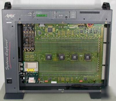
Aptix/Mentor Graphics MP4CF System Explorer Emulation System
Comes with what you see in the pictures. If you don't see it, you probably wont get it.
Specifications are from Aptix and may vary slightly due to upgrades, options, or revisions this unit may or may not have.
The unit powers up and passes self-test as far as I can tell. It was removed from service from Intel in working condition. I do not have the expertise to test the system after that.
* FPCB-MP4C, Part Number: 240005-AB, Serial Number: 13050, Assembly Number 240135 Rev. AB, ET Rev. 1.0
* Contains 4 FPIC Programmable Components, Part Number: AX1024FR 023/4559
Low-Skew Clock Circuit Board:
* Part number is scratched off until the -AA and there was a part that said 241210-AD
Link to the Datasheet: Aptix System Explorer Datasheet
The System Explorer MP4CF is optimized for prototyping ciruits with wide internal busses and extensive interconnect requirements. The MP4CF architecture provides maximum routing flexibility for prototypes incorporating many FPGAs and only a few fixed-pin prototyping components (such as a CPU or DSP). Use the MP4CF for building high density prototypes of networking and multimedia systems.
* More than 3 million ASIC gates and 10 Mbits block memory with Xilinx Virtex V2000E modules (not included unless seen in pictures)
* Upgradable with future FPGA modules (Prototyping area of 2,880 pins with programmable interconnect currently supports up to 20 FPGAs)
* Multi-system configurations can be setup with Aptix Consulting Services
Through Probe Bus: more than 2,500
Off-Board I/O to Target System:
* Additional off-board I/O available through cable connectors on FPGA prototyping modules
Supply Voltage: 100-230V AC auto-ranging, 48 ~ 62 Hz
Power Consumption: 5A (max), 400W (max)
Power Supplies for Prototyping Components: (10 A max. each)
* Interactive configuration via Ethernet
* Stand-alone configuration via onboard FLASH memory, stores up to four designs simultaneously
* Power-on self test for system hardware
* Connectivity self-test for FGPA prototyping modules mounted in system
For More Pictures Please Click the Following:
* Picture 4 - Indicators and Display
* Picture 5 - Microcontroller Circuit Board
* Picture 6 - Clock Circuit Board
* Picture 7 - 4 FPIC x 4 Interfaces
* Picture 8 - MP4C FPIB Pod Interface Logo
* Picture 9 - 40-Pin Logic Analyzer Connector Legend
* Picture 10 - Communication Interfaces