Bakersfield will thrive again! Moderated business marketplace list > Quailwood
> Science and Lab
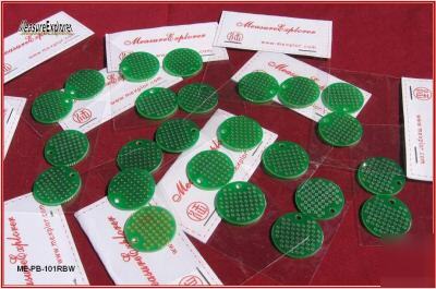
> Me-pb-101RW wireless circuit proto prototype pcb board
Me-pb-101RW wireless circuit proto prototype pcb board
MeasureExplorer prototype board product: ME-PB-101RW, Single Layer wireless copper pattern 1" diameter Circular Board, 24
We are looking for physical store carrier for this item
You can use this board to make your own design LED lighting disk
You get 24 boards in the package!
I am sure you want your prototype circuit looks clean, like a real PCB board, and less interfere between components, here is the solution. You may feel it is strange, unlike the way you do before, with this board, instead of doing soldering wires to make the connection between components, you need to do cutting wire. I do not know if you like to do this or not, but I have to tell you, the finished assembly with this board never looks like bread, it never be "bread board" at all, it is a real PCB without your special CAD layout.
Copper pads on the board are all connected together by 0.02" thick wire on the board.
2. Layout the positions of component on the board on pattern sheet paper.
3. Mark out connections that you do not need on the board
4. Cut off all the marked connections that you do not need by regular cutter of small diller.
5. Solder components on the board. You get very clear and low cross-talk prototype circuit.-
Single copper layer prototype board
NON-Plated through holes with diameter 39mil and 0.1 inch grid
All copper pads are connected through 0.02inch copper wire
Round shape with 1.0 inch diameter
1 4-40 NON-plated screw holes are located
Mechanically can couple with any MeasureExplorer prototype boards
In the past tens of years, I experienced so many difficulties when I worked on circuit prototyping. I am sure, you can understand me well since we are walking in the same way. Before checking the board specification, please allow me to ask you some questions. Then I am pretty confident, you are going to know the whole purpose of MeasureExplorer design of prototype board.
Actually all my thinking about circuit prototyping process is for a system relatively larger, which means usually it is hard to combine all the components onto a single board. However, on the other hand, it is always easier if you divide your whole system circuit into small parts. No matter your prototyping is for design testing or just build one for your special use, dividing your system into small functional module is helpful for your building and testing. And further, your own functional modules are useful for your future experiment. You can just take it form your hardware file to use without repeating the soldering again. Here is my first question. Have you ever had difficulty on mechanical coupling of your different functional module boards, in order to get stable, reliable electrical connection, and make the system fit into your special space?
Of course, you might be skilled on soldering, however, do you think it is difficult to sold more than 2 wires together at a point on your board? This is my second question, you can find a solution from MeasureExplorer prototype board products.
People give prototype board another name, bread board, which means that a lot of connection wires jumping across the board, finally building a thing like a bread. In fact, these jumping wires are so bad for signal transfering and are very easy to pick up noise, generate electrical and magnetic interference. So my third question is that have you ever had a dream making your prototype board like a real PCB, but without expensive cost and a lot of time on CAD design and waiting for the coming of your ordering?
When you do ultra high impedance circuit prototyping, base material of board, like FR4, is not a ideal insulator. Current leaking of board material can cause you losing the high impedance advantage of the IC you want to use. Here is a question for you. Do you know how to deal with ultra high impedance circuit in your prototyping process?
Surface mount components are widely used in current electronics design. I am sure you do not want to take a corresponding DIP part as your target in your experiment, in fact, some components have no corresponding DIP package for you choose at all. The question here is Do you get used to have a surface mount adapter in your prototyping?
These are what MeasureExplorer is trying to solve.