Bakersfield will thrive again! Moderated business marketplace list > Venola
> Exports
> LS7184 encoder to counter interface chip - out:step/dir
LS7184 encoder to counter interface chip - out:step/dir
LS7184Encoder to Counter Interface Chip in DIP-8 package.Input: incremental encoder A+B :::: Output: Step and direction signal.For servo motor or stepper motor position verify & servo drive controller.example: step loss measurement with encoder (and counter) or manual positioning the CNC with electronic handwheel. (encoder inside)... The chip can also working: 4x, 2x, 1x mode. Example: 500cpr encoder 4x mode = 2000 impulse, 2x mode = 1000 impulse, 1x mode = 500 impulse output each encoder cycle. Data Sheet: http://cnc.hunbay.com/LS7184/LS7184_DataSheet.pdf Example circuit: http://cnc.hunbay.com/LS7184/LS7184_encoder.jpg Timing diagram: http://cnc.hunbay.com/LS7184/LS7184_timing.jpg_______________________________________________________________________________________________________________ Features:
X4, X2 or X1 resolution multiplication !!!
Operates from 3V to 5V power supply
The LS7184 allow incremental encoders to drive standard up/down counters. Connect the encoder quadrature outputs to the A & B inputs. Pin Descriptions: Pin 1 (Rbias Input):
Input for external component connection. A resistor connected between this input and ground adjusts the output pulse width. See Rbias Resistor Value vs. Timing Table for further information.. Pins 4 & 5 (A & B Inputs):
Connect to the A and B quadrature outputs of the encoder. Both inputs have debounce filters. Minimum pulse width is set at 300ns. There is no maximum limit. Input current is less than 1µA. The A and B inputs can be swapped to reverse the direction of the external counters. Pin 6 (Mode Input):
Mode is a 3-state input to select resolution X1, X2 or X4. The input quadrature clock rate is multiplied by factors of 1, 2 or 4 in X1, X2 or X4 modes respectively in producing the output Up/Dn clocks. X1, X2 or X4 modes are selected by input logic levels as follows:Mode = 0 VDC = X1 Selection
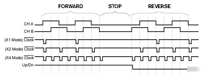
In X4 mode, one pulse is generated for each A/B state change. In X1 mode, one pulse is generated per quadrature cycle. In X2, two pulses per quadrature cycle.
This output steers the external counter up or down. High = Up (A leads B), Low = Down (B leads A). Pin 8 (Clock Output):